

A six-load-cell truck scale usually does not fail all at once.
More often, the first sign is something small: the zero begins to drift, the same truck gives slightly different readings, one end of the weighbridge seems light, or the scale becomes unstable after rain.
When that happens, it is easy to blame the load cells immediately. But in the field, the actual cause may be a load cell, cable, junction box, foundation problem, debris under the deck, or the weighing indicator itself.
The fastest way to find the fault is not to replace parts one by one. It is to narrow the problem down section by section.
1. First, Understand How the Six Load Cells Work Together
A typical six-load-cell truck scale uses three weighing points on each side of the platform.
For example:
- Front Left — LC1
- Middle Left — LC2
- Rear Left — LC3
- Front Right — LC4
- Middle Right — LC5
- Rear Right — LC6
The actual numbering depends on the manufacturer, so always check the wiring diagram.
Each load cell measures part of the vehicle load. In an analog system, the six signals normally enter a junction box and are then sent to the weighing indicator.
2. Start With the Symptom
Before testing individual load cells, observe exactly how the truck scale behaves.
| Symptom | Possible Causes |
| Will not return to zero | Debris, mechanical binding, moisture, load cell problem |
| Weight slowly drifts | Moisture, cable, unstable load cell |
| Reading jumps randomly | Loose wiring, cable damage, electrical noise |
| One section reads differently | Load cell, mounting or mechanical problem |
| Problem after rain | Junction box, cable or load cell moisture |
This first observation often tells you where to start.
3. Check the Mechanical Condition First
Before using a multimeter, inspect the weighbridge structure.
Look for:
- mud or stones under the deck
- material touching the platform
- damaged check rods or stops
- loose load cell mounts
- bent steel parts

A truck scale must transfer vehicle weight freely to the load cells.
If the deck touches the foundation or another structure, part of the weight may bypass the load cells and cause an error.
So a weighing problem does not always mean an electrical fault.
4. Check Zero Stability
Remove all loads from the scale and observe the indicator.
If the reading continually moves, for example:
0 → +20 kg → +45 kg → -15 kg → +30 kg
the system is not stable.
Common causes include:
- moisture
- loose terminals
- damaged cable
- unstable load cell
- electrical interference
- mechanical binding
If the problem becomes worse after rain, inspect the junction box and cable connections first.

5. Inspect the Six Load Cell Cables
Follow each load cell cable toward the junction box.
Look for:
- cuts or crushed cable
- exposed conductors
- loose cable glands
- corrosion
- damaged conduit
- old repair joints
A damaged cable can produce unstable or incorrect readings even when the load cell itself is still working.
6. Inspect the Junction Box
On a six-load-cell analog truck scale, the junction box is one of the most important troubleshooting points.
This is where the six load cell signals normally come together.
After safely isolating the equipment where required, check for:
- water or condensation
- corrosion
- loose terminals
- damaged wire strands
- burned surge components
A junction box problem can easily look like a bad load cell.
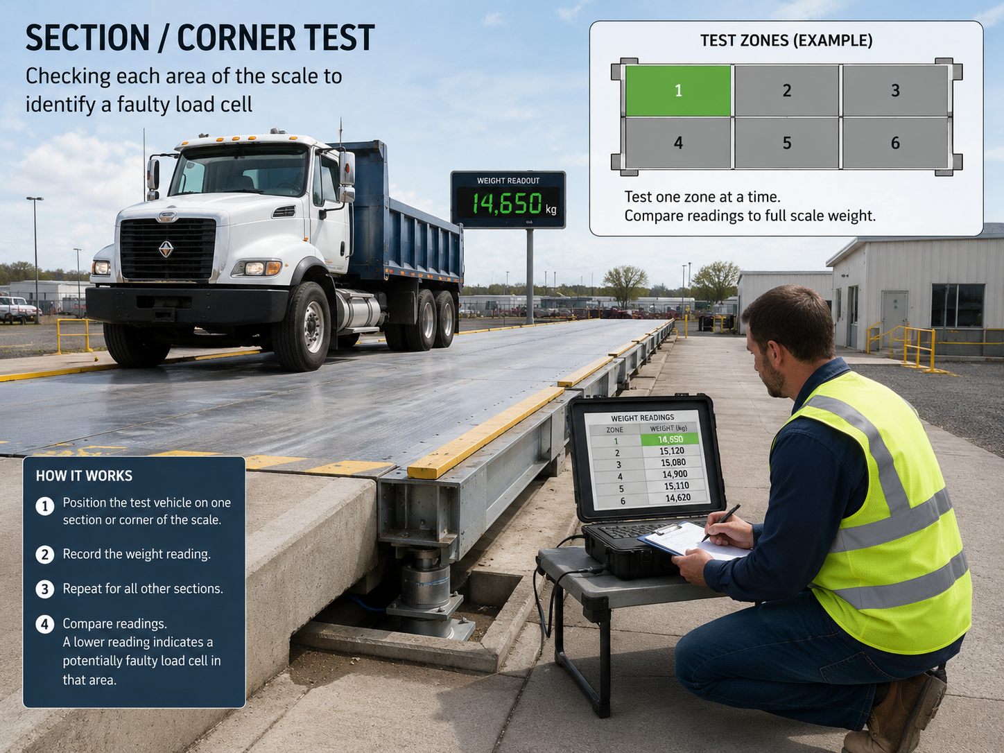
7. Perform a Section Test
One of the fastest ways to locate a problem on a six-load-cell truck scale is to compare different areas of the platform using the same test load.
For example:
| Test Area | Reading |
| LC1 | 10,020 kg |
| LC2 | 10,010 kg |
| LC3 | 10,025 kg |
| LC4 | 10,015 kg |
| LC5 | 9,450 kg |
| LC6 | 10,020 kg |
The LC5 section is clearly different.
This does not immediately prove that LC5 is damaged.
First check that area for:
- mechanical interference
- load cell mounting
- cable condition
- junction box connection
- load cell signal
This is much more reliable than replacing the load cell immediately.
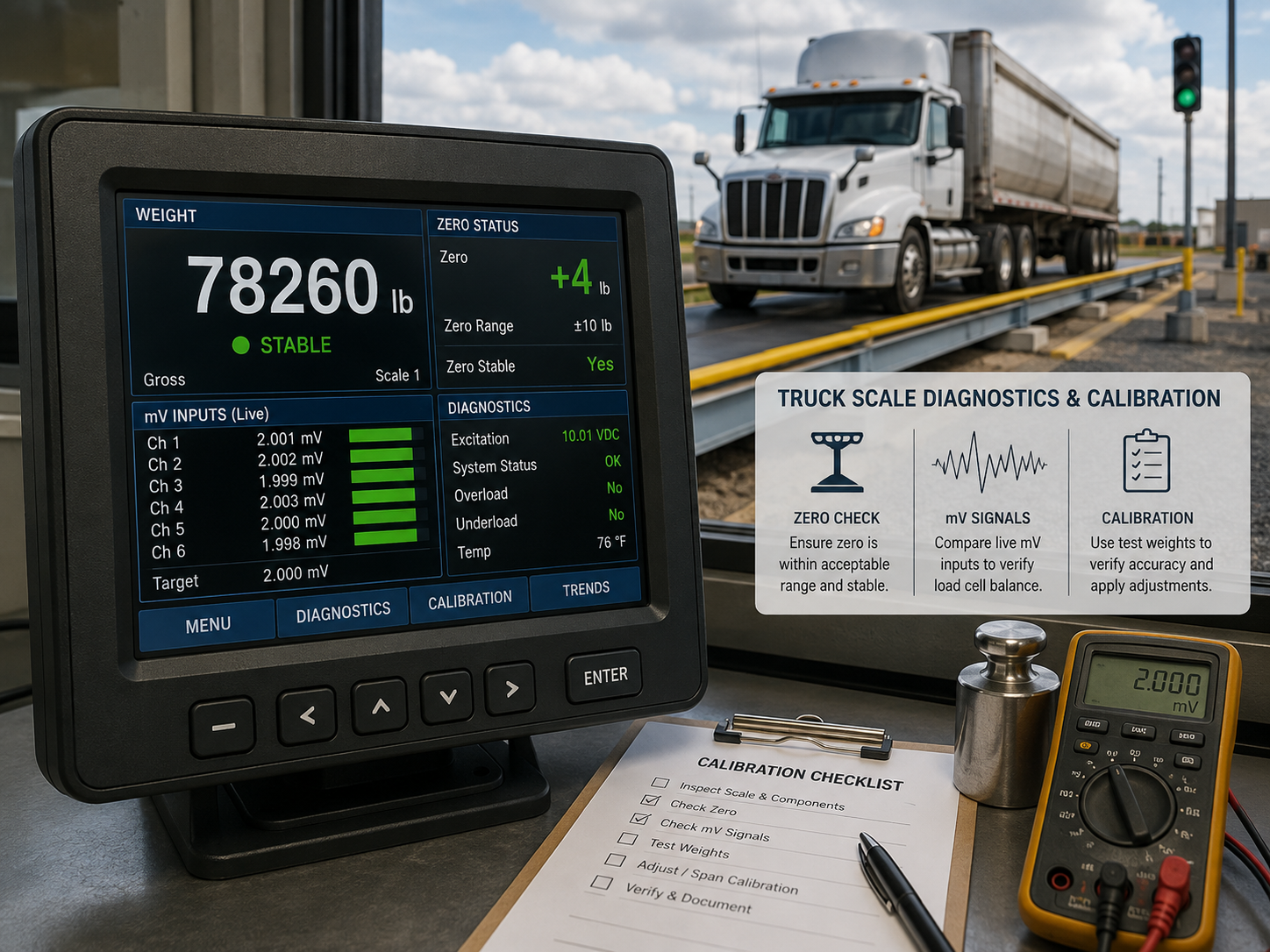
8. Compare Load Cell Output Signals
If the mechanical condition looks normal, compare the electrical output of the six load cells.
A strain-gauge load cell receives excitation voltage and produces a small millivolt signal.
For example:
| Load Cell | Output |
| LC1 | 7.4 mV |
| LC2 | 7.5 mV |
| LC3 | 7.6 mV |
| LC4 | 7.5 mV |
| LC5 | 2.0 mV |
| LC6 | 7.4 mV |
LC5 is clearly behaving differently.
However, do not expect every load cell to have exactly the same output.
The actual signal depends on vehicle position, load distribution, load cell capacity and excitation voltage.
The important question is whether one load cell is significantly different from the others under similar conditions.
9. Check Excitation Voltage
If a load cell does not receive the correct excitation voltage, its output will also be incorrect.
A useful troubleshooting rule is:
All six load cells have abnormal excitation
Check:
Indicator → Home-Run Cable → Junction Box
Only one load cell is abnormal
Check:
Junction Box → Individual Cable → Load Cell
This helps determine whether the problem affects the entire system or only one weighing point.
10. Check Resistance and Insulation if Necessary
If one load cell remains suspicious, resistance testing can provide more information.
Possible checks include:
- excitation resistance
- signal resistance
- cable continuity
- insulation to the load cell body
Do not use one generic resistance value for every load cell.
Instead:
Measure → Compare with manufacturer specifications → Compare with the other five identical cells
Moisture-related insulation problems are especially worth checking if the scale becomes unstable after rain.
11. If All Six Load Cells Look Normal
If all six load cells appear normal, move to the components shared by the entire system.
Focus on:
- junction box
- home-run cable
- weighing indicator
- grounding
- electrical interference
If the signal is correct at the junction box but incorrect at the indicator, the home-run cable or indicator becomes more suspicious.
12. Do Not Recalibrate Too Early
Recalibration is not a repair.
If the real problem is moisture, cable damage, mechanical binding or a failing load cell, calibration may temporarily hide the error but will not remove the cause.
A better sequence is:
Find the fault → Repair → Check section balance → Calibrate
If a load cell is replaced, check zero stability, section balance and calibration again.
13. Quick Troubleshooting Flow
For most six-load-cell truck scale problems, this sequence works well:
Mechanical inspection→Check zero stability→Inspect load cell cables→Inspect junction box→Perform section test→Identify suspicious load cell→Compare excitation and mV output→Check resistance/insulation if needed→Check home-run cable and indicator→Repair and calibrate
This is usually faster than replacing load cells one by one.
14. When Should a Load Cell Be Replaced?
A load cell should normally be replaced only when the tests clearly point to the cell itself.
Typical signs include:
- missing or abnormal signal
- severe zero drift
- abnormal resistance
- poor insulation
- physical damage
- confirmed moisture ingress
- repeated instability traced to one cell
If the problem is only a loose terminal or external cable, replacing the whole load cell may not be necessary.
15. FAQ
Use a section test to identify the problem area, then inspect the mechanical condition, cable and junction box connection. Finally compare excitation, millivolt output, resistance and insulation with the other load cells.
Yes. Because the final weight is calculated from the combined signals of all load cells, one abnormal cell can affect total weight or cause section errors.
Common causes include moisture in the junction box, damaged cable insulation or water entering a load cell.
Normally yes. Check zero stability and section balance first, then complete the final calibration.
16. Conclusion
Troubleshooting a 6 load cell truck scale is mainly about finding where the error begins.
If only one section reads incorrectly, focus on the mechanical structure, load cell, cable and connection in that area.
If the entire scale is unstable, check the junction box, home-run cable, grounding and weighing indicator.
The most practical troubleshooting sequence is:
Mechanical inspection → Section test → Cable and junction box check → Load cell signal comparison → Indicator check → Repair → Calibration
A six-load-cell truck scale has six sensors, but a weighing problem does not always mean a sensor has failed.

Need customized model matching your production line, technical drawings and accurate quotation?
Submit your inquiry now, our engineering sales team will send full solution within 24 working hours.