
A belt scale can be calibrated correctly and still perform poorly.
In many cases, the problem starts before calibration: the scale was installed where the conveyor itself keeps changing the forces acting on the weighing system.
The best installation point is not simply a place where the scale physically fits.
It is a section where:
- the belt geometry is stable
- the material has settled
- the idlers can be aligned
- the weigh frame can move without interference
- belt speed can be measured reliably
A useful way to judge a proposed location is:
Will the scale measure mainly material load, or will the conveyor add other forces to the measurement?
1. Start With the Conveyor, Not the Scale
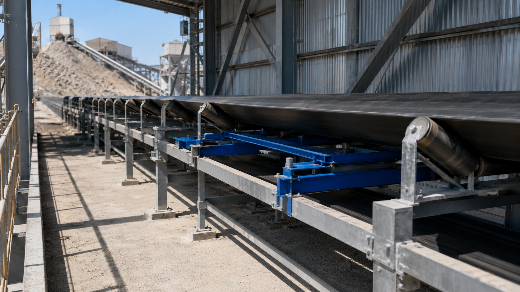
Before marking bolt holes, look at how the conveyor behaves while it is running.
A section that appears straight and stable while stopped may behave differently when:
- the belt is fully loaded
- belt tension increases
- the structure flexes
- material loading changes
The weighing zone should remain mechanically similar across normal operating conditions.
Look at:
- belt contact with the idlers
- idler height
- belt tracking
- structural movement
- material profile
- nearby changes in conveyor geometry
If these conditions change significantly between an empty belt and full production, the weighing system will have to measure through those changes.
That makes stable weighing harder.
2. Do Not Install Too Close to the Loading Chute
Material should have time to settle before it reaches the weighing zone.
Directly after a chute, material may still be:
- falling
- bouncing
- accelerating
- sliding
- moving laterally across the belt
The load cells then see dynamic forces in addition to the normal material load.
This is why “distance from the chute” should not be treated as one fixed number for every conveyor.
The better question is:
Has the material finished changing motion before it reaches the scale?
For example, two conveyors may both carry 100 t/h.
On one conveyor, the material forms a stable profile shortly after loading.
On another, large lumps may continue bouncing and redistributing several meters downstream.
The correct scale location will not necessarily be the same.
A simple field check is to watch the belt at normal production speed.
If the material profile is still visibly changing at the proposed weighing point, the location is probably too close to the loading point.
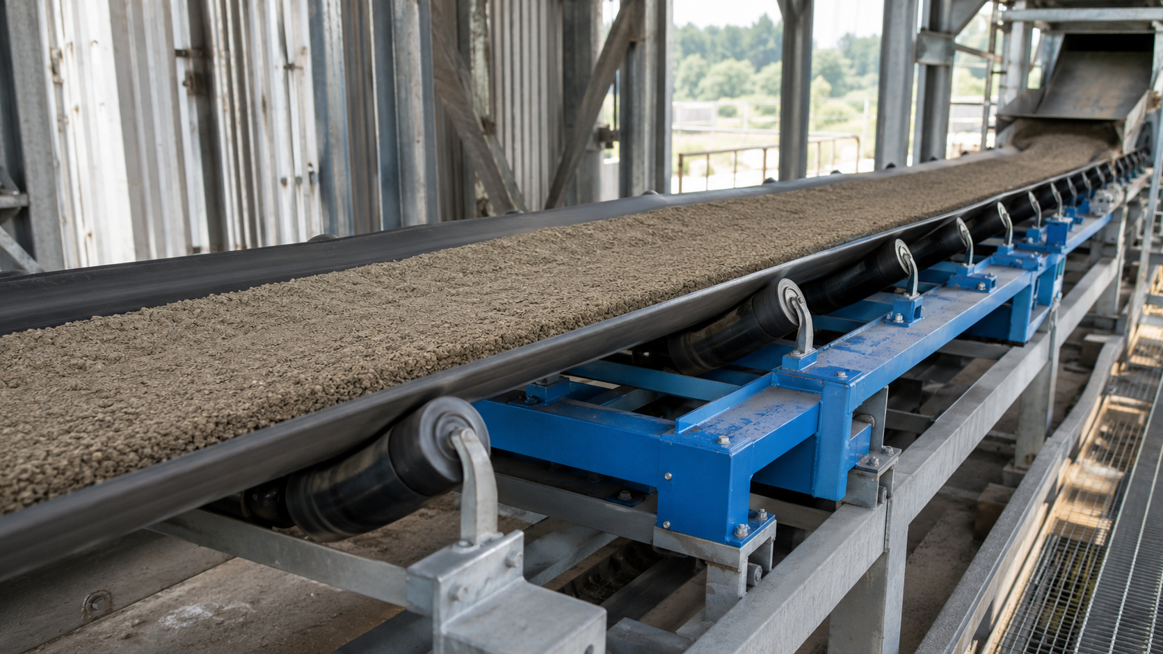
3. Belt Tension Becomes a Problem When Geometry Converts It Into Vertical Force
Belt tension is always present.
That does not automatically create weighing error.
The problem appears when the belt changes direction around the weighing zone.
For example, if the scale is close to a vertical curve, belt tension can create an additional vertical force component at the weigh idlers.
The load cells cannot distinguish that force from material load.
This is why a belt scale should generally be kept away from:
- convex curves
- concave curves
- major transition sections
- locations where belt geometry or tension changes rapidly
The important issue is not tension by itself.
It is:
belt tension + conveyor geometry.
4. A Few Millimeters of Idler Error Can Become a Weighing Error
The weigh idler and the nearby approach and retreat idlers should form a consistent belt-supporting plane.
Suppose the weigh idler sits slightly higher than the surrounding idlers.
The belt has to rise over it.
Because the belt is under tension, this small geometric change creates additional force on the weighing structure.
The scale may then read high.
If the weigh idler is low, the load path changes in a different way.
This is why idler alignment should not be judged by eye alone.
Use a string line, wire, laser, or another suitable method to check the weigh idler and nearby idlers.
Check:
- height
- spacing
- squareness
- consistent belt contact
One field clue is especially useful:
If weighing performance changes immediately after idler maintenance, check alignment before changing the span factor.
Changing calibration may hide the effect temporarily, but it does not restore the original geometry.
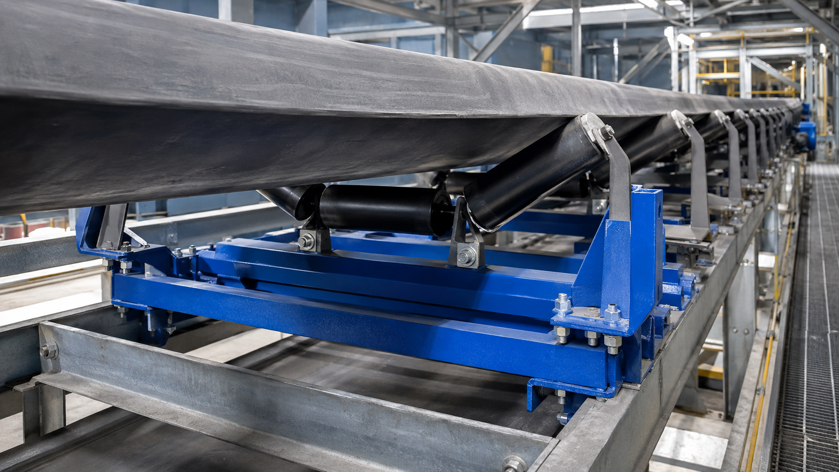
5. Check Whether the Weigh Frame Is Truly Free
The weigh frame must respond to material load without unintended mechanical restraint.
Check for contact with:
- conveyor steelwork
- guards
- covers
- accumulated material
- cable trays
- brackets
- tightly routed cables
Even light contact can matter.
If part of the material load follows another mechanical path instead of passing through the load cells, a force shunt is created.
The scale may read low.
If another structure pushes on the weigh frame, the reading may go high.
This is one reason a static calibration test can sometimes look acceptable while production results are wrong.
The interference may only appear when:
- the belt is loaded
- the conveyor structure deflects
- vibration increases
- buildup reaches the weigh frame
Inspect the scale under running conditions, not only while the conveyor is stopped.

6. Belt Tracking Should Already Be Stable Before the Scale
A belt that continuously moves from side to side changes the mechanical condition of the weighing zone.
It may change:
- belt contact with the idlers
- side loading on the weigh frame
- material distribution across the belt
The scale should not be used as the point where a tracking problem is corrected.
Tracking should be corrected elsewhere so that the belt enters the weighing zone already running consistently.
This becomes more important on wide belts and where material frequently loads off-center.
A dual-load-cell arrangement can reduce sensitivity to off-center loading, but it cannot turn unstable tracking into a stable conveyor condition.
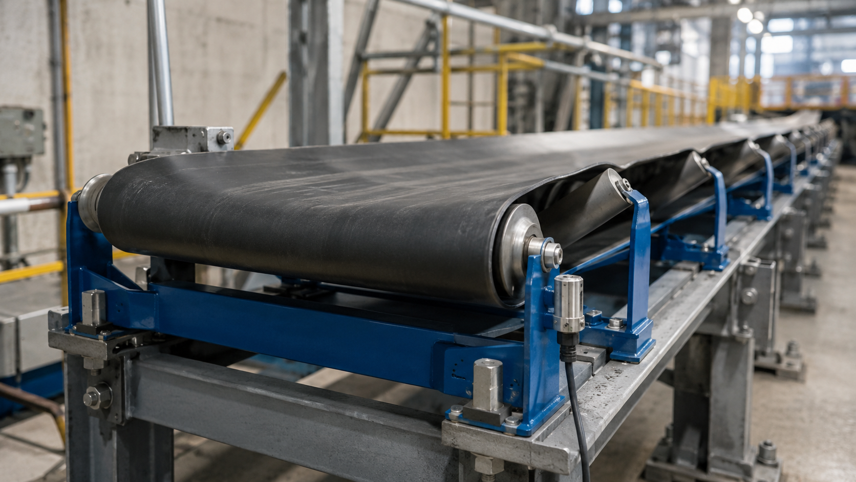
7. Check Belt Loading, Not Only Tons per Hour
One installation detail is often missed because plants usually think in tons per hour.
A belt scale actually works with material load per unit length and belt speed.
The relationship is:
Flow = Belt Load × Belt Speed

For the same production rate, a faster belt carries less material per meter.
For example, at 40 t/h:
- at 0.5 m/s, belt loading is about 22.2 kg/m
- at 2.0 m/s, belt loading is about 5.6 kg/m
The production rate is identical.
But the second conveyor gives the weighing system only one-quarter of the material signal per meter.
The same mechanical disturbance or zero variation can therefore have a larger percentage effect.
When evaluating an application, record:
- minimum and maximum flow
- belt speed
- belt width
- expected belt loading in kg/m
Do not evaluate the application using maximum t/h alone.
8. Material Must Travel With the Belt
The speed sensor measures belt travel.
The calculation assumes that the material travels with the belt.
If material slides relative to the belt, that assumption begins to fail.
This may happen with:
- steep conveyor inclines
- unsuitable belt speed
- low-friction material
- unstable loading conditions
This distinction matters:
An accurate belt-speed signal does not prove that material speed equals belt speed.
If material is visibly sliding in the weighing zone, improving the speed sensor will not solve the underlying problem.
The conveyor condition itself needs attention.
9. The Speed Sensor Should Measure Actual Belt Travel
The speed sensor provides one of the two basic measurements used to calculate flow.
Flow = Belt Load × Belt Speed
If the speed signal is 1% high, calculated flow will also be approximately 1% high when the load measurement is correct.
The installation should avoid conditions where:
- a measuring wheel can slip
- sensor contact changes
- an encoder coupling can loosen
- the measured drive rotation does not represent actual belt travel
A speed value can look perfectly stable and still be wrong.
The useful check is:
Does the measured speed agree with actual belt travel?
This is especially important on variable-speed conveyors.
A scale that performs correctly at one speed but not another may have a speed-measurement problem rather than a span-calibration problem.
10. Do Not Use Calibration to Hide an Installation Error
Suppose a material test shows that the belt scale reads 1% high.
It is tempting to reduce the span factor by 1%.
The next test may pass.
But what caused the original error?
If it came from:
- a high weigh idler
- an incorrect speed signal
- mechanical contact
- unstable belt tracking
- changing material impact
then calibration has not removed the cause.
It has created a second error that happens to cancel the first under that test condition.
When belt speed, loading, tension, or idler condition changes, the error may return.
A better sequence is:
mechanical condition → running zero → calibration → material verification
not:
material test → change span → hope the problem is solved
11. Use the Running Zero as an Installation Check
Before final calibration, run the conveyor empty.
Do not look only at whether the display is close to zero.
Watch how the zero behaves over complete belt revolutions.
A useful distinction is:
A repeatable zero pattern is different from random zero drift.
If the zero changes at the same position every belt revolution, investigate:
- the belt splice
- local belt thickness
- damaged belt sections
- recurring belt contact
If the zero gradually moves over time, check:
- material buildup
- belt tracking
- mechanical contact
- tension changes
If the signal jumps randomly, also inspect:
- load-cell wiring
- junction boxes
- grounding
- electrical noise
The running zero is therefore more than a calibration step.
It is one of the first dynamic checks of whether the installation is mechanically and electrically stable.
12. Before Calibration, Check These Conditions
The system is usually ready for calibration when:
- the weigh and adjacent idlers are aligned
- the weigh frame is mechanically free
- the belt tracks consistently
- the empty belt maintains proper contact with the weigh idlers
- material is settled before entering the scale
- material does not slip through the weighing zone
- the speed signal represents actual belt travel
- the running zero is repeatable
If one of these conditions is still changing, calibration should wait.
Stable mechanics first. Calibration second.
13. Installation Considerations for the LCS-Series
The LCS-Series high-accuracy conveyor belt scale uses a floating-balance weighing structure with dual Keli load cells.
The floating structure is designed to reduce unnecessary force-transfer paths, while the dual-load-cell arrangement helps reduce sensitivity to off-center loading.
Those features improve the weighing structure, but they do not remove installation requirements.
For an LCS-Series application, useful information before installation includes:
- belt width
- minimum and maximum flow
- belt speed
- expected belt loading in kg/m
- conveyor incline
- material type
- loading-point location
- nearby vertical curves
- normal material distribution across the belt
This information is more useful than maximum capacity alone.
A 500 t/h conveyor can be an easy or difficult weighing application depending on how that tonnage is carried through the weighing zone.
14. The Main Point
A good belt-scale installation gives the weighing system a simple, repeatable mechanical condition.
The belt arrives stable.
The material has settled.
The idlers define a consistent plane.
The weigh frame is free.
The material travels with the belt.
The speed sensor measures actual belt travel.
When those conditions are present, calibration becomes correction of a stable measurement.
When they are not, calibration often becomes an attempt to compensate for a conveyor condition that keeps changing.
So the most useful installation question is not:
“Can we mount the scale here?”
It is:
“Will the scale see the same relationship between material load, belt travel, and mechanical force every time the conveyor runs?”

Need customized model matching your production line, technical drawings and accurate quotation?
Submit your inquiry now, our engineering sales team will send full solution within 24 working hours.