
A belt scale can use an excellent load cell and still produce poor results in the field.
The reason is simple: the load cell only measures the force that reaches it. It does not know whether that force came from the material, belt tension, a misaligned idler, material buildup, or mechanical contact.
That makes belt scale accuracy a system problem, not just a sensor problem.
A better question is:
How much of the force reaching the load cell actually represents the material being conveyed?
1. Accuracy Starts With the Useful Material Signal
A belt scale measures material on top of an existing mechanical background.
The belt has weight, the idlers rotate, the conveyor vibrates, and belt tension is always present.
Suppose a zero-related offset is equivalent to: 0.5 kg/m
At a material loading of: 150 kg/m
the relative effect is about: 0.33%
At: 20 kg/m
the same offset becomes: 2.5%
The disturbance did not increase. The useful material signal became smaller.
This is why low-loading applications are often more sensitive to zero drift, vibration, and tare variation.
It also explains why kg/m can be more useful than t/h when judging the weighing condition.

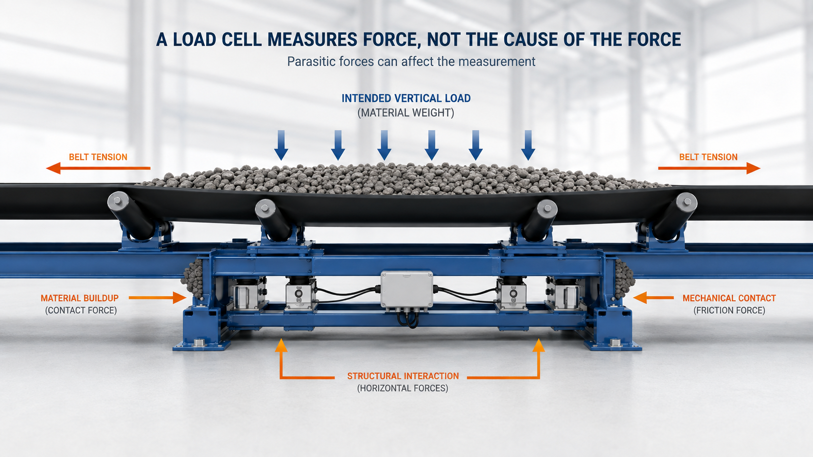
2. A Load Cell Measures Force, Not the Cause of the Force
The scale wants to measure one thing:
the vertical force created by the material.
But other forces can enter the same measurement path.
Examples include:
- belt tension acting through poor geometry
- material buildup
- vibration
- mechanical contact
- unstable loading
These unwanted forces are often called parasitic forces.
Good belt scale design is partly about transferring the material load clearly while preventing unrelated forces from reaching the sensors.
This is why mechanical design matters as much as load-cell specification.
3. Why Idler Alignment Becomes Weight Error
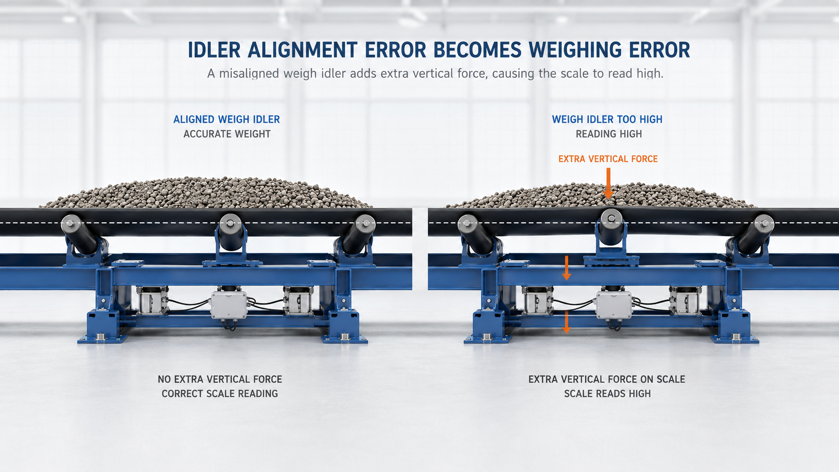
Suppose the weigh idler sits slightly higher than the adjacent idlers.
The belt must rise as it enters the weighing zone.
Because the belt is under tension, this geometry creates an extra vertical force on the weigh idler.
The load cell measures it.
From the sensor’s point of view, that extra force looks like material weight.
This is why idler alignment is not just an installation detail.
Poor alignment changes the force path.
If weighing error appears after idler replacement or conveyor maintenance, inspect the mechanical geometry before changing calibration.
4. Material Should Be Settled Before It Reaches the Scale
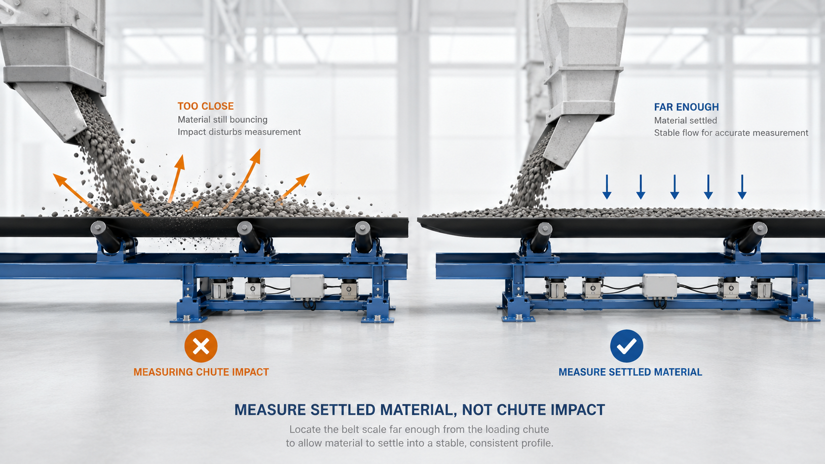
A belt scale should measure material load, not loading impact.
If the scale is too close to a chute or loading point, material may still be:
- bouncing
- accelerating
- sliding
- changing profile
The load cells then see dynamic forces in addition to normal material weight.
A better weighing condition is created when the material has enough distance to settle before entering the weighing zone.
A useful rule is:
Measure settled material, not chute impact.
5. Speed Error Passes Directly Into Flow Error
The basic relationship is:
Flow = Belt Load × Belt Speed
If belt load is correct but the speed signal is 1% high, the calculated flow will also be about 1% high.
This creates a common troubleshooting mistake.
If a technician reduces the weighing span by 1% to compensate, the final total may look correct—but now one error is simply cancelling another.
If the speed sensor is later corrected, the weighing result becomes wrong again.
So:
Do not use span calibration to compensate for a speed error.
Also remember:
A stable speed signal is not automatically an accurate speed signal.
The sensor must represent the actual belt movement through the weighing zone.

6. Accuracy and Repeatability Are Different
Consider three tests:
+1.02%
+0.98%
+1.01%
The scale is consistently high.
Its repeatability is good, but its accuracy is poor.
Now compare:
−0.30%
+0.50%
−0.20%
The average may look closer to zero, but the results are not stable.
These two conditions require different responses.
A stable bias can often be corrected after the cause is understood.
An unstable measurement should first be investigated.
A practical rule is:
Repeatability first. Correction second.

7. The Error Pattern Often Tells You Where to Look
A single error number is less useful than the way the error changes.
| Error Pattern | Check First |
| Similar percentage error at low and high flow | Span calibration or proportional bias |
| Error becomes much worse at low flow | Zero stability or low material signal |
| Error changes with belt speed | Speed measurement |
| Error repeats each belt revolution | Belt splice or local belt condition |
| Error appears after idler maintenance | Alignment or mechanical geometry |
| Results vary widely between tests | Loading stability, vibration, mechanics |
| Calibration passes but material test fails | Dynamic conveyor condition |
This table is not a fault code.
It is a way to narrow the investigation before changing parameters.
8. Calibration Cannot Fix Every Accuracy Problem
Calibration can correct a stable measurement relationship.
It cannot permanently fix:
- misaligned idlers
- unstable zero
- poor speed measurement
- material buildup
- restricted weigh-frame movement
- changing material loading
If the scale needs frequent span adjustments to stay aligned with production totals, the span factor may not be the real problem.
A useful warning sign is:
If the calibration factor keeps changing, ask what changed physically before changing it again.
9. How Mechanical Design Helps
The KELISCALES LCS-Series uses a floating-balance weighing structure with dual Keli load cells.
The design is intended to reduce unnecessary force-transfer links and improve response when material is not perfectly centered on the belt.
These features help control some important error sources.
But final performance still depends on:
- correct idler alignment
- stable material loading
- reliable speed measurement
- proper calibration
- suitable scale location
A high-accuracy belt scale should not be understood as a system with no error.
It is better understood as:
a system designed to reduce and control the dominant sources of error.
10. The Main Point
Conveyor belt scale accuracy depends on the complete measurement chain.
When a scale becomes inaccurate, start with these questions:
Is the useful material signal strong enough?
Is unwanted force entering the weighing path?
Is belt speed being measured correctly?
Are repeated test results stable?
Does the error change with flow, speed, or conveyor condition?
Those questions usually reveal more than comparing load-cell accuracy specifications alone.

Need customized model matching your production line, technical drawings and accurate quotation?
Submit your inquiry now, our engineering sales team will send full solution within 24 working hours.