
A hopper weighing project may start with a simple calculation:
Hopper dead weight: 2.5 t
Maximum material: 8 t
Four support points
The theoretical average is:
(2.5 + 8) ÷ 4 = 2.625 t per support
That number is useful, but it is not enough to select the load cells.
A real hopper rarely loads every support point equally. Filling position, material distribution, connected piping and vibration can all change the force reaching each load cell.
The better question is:
What is the highest realistic load that one support point may see?
1. Average Load Is Not the Maximum Support Load
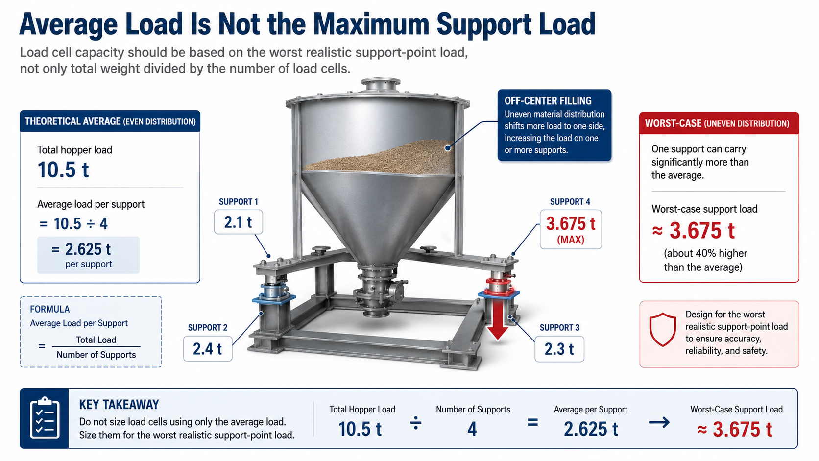
Suppose the full hopper weighs 10.5 t.
If one support temporarily carries 35% of the total load because material enters from one side, that support sees about:
10.5 × 35% = 3.675 t
This is already well above the theoretical average of 2.625 t.
And it still does not include filling impact, vibration or external piping forces.
So load-cell capacity should be based on the worst realistic support-point load, not simply:
total weight ÷ number of load cells.
At the same time, unnecessarily large load cells are not automatically better. Normal working load should still use a reasonable part of the available measurement range.
2. Piping Can Become Part of the Weighing System
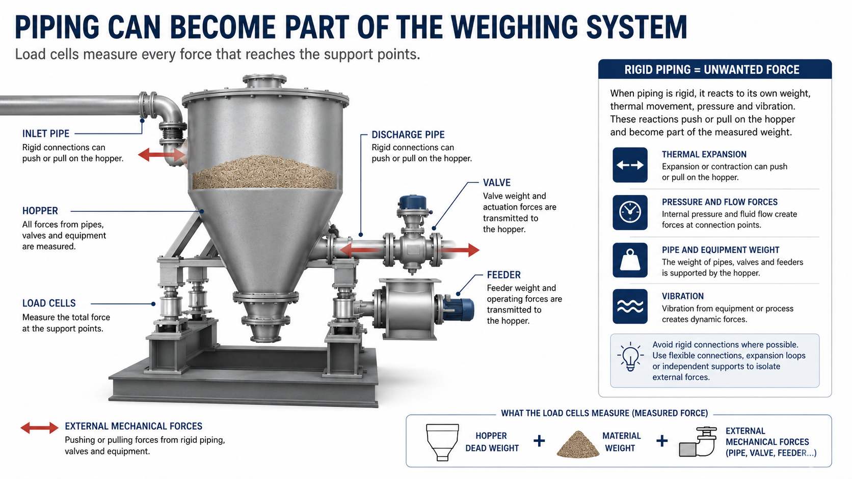
A load cell does not know whether a force comes from material or from a pipe.
It measures whatever force reaches the support point.
So the real measurement can be thought of as:
Measured Force = Hopper + Material + External Mechanical Forces
Rigid inlet pipes, discharge pipes, valves, feeders and dust-collection connections can all introduce unwanted force.
This is why a piping drawing can sometimes be more useful than another page of load-cell specifications.
3. Flexible Connections Help, but Installation Still Matters
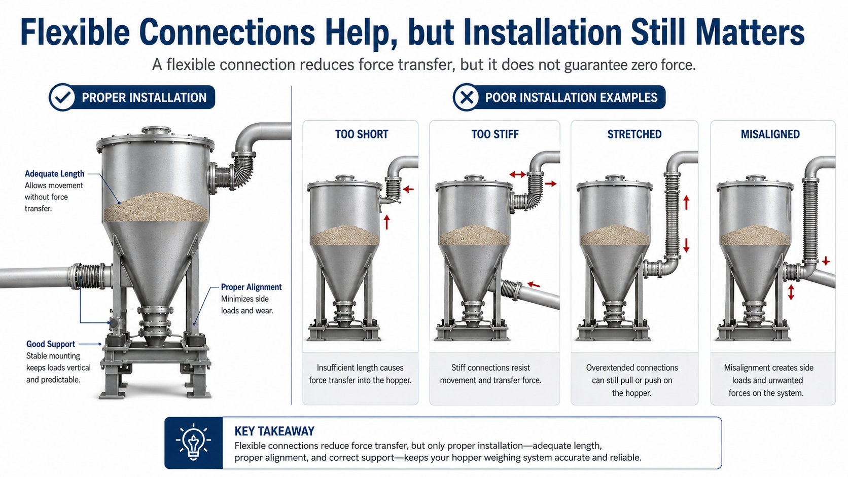
Flexible connections are commonly used to reduce unwanted force transfer.
But “flexible” does not mean “zero force.”
If a connector is too short, too stiff, stretched or misaligned, it can still pull or push on the hopper as the vessel moves under load.
So the real question is not:
“Is there a flexible connection?”
“Can the hopper move as required without the connection creating significant additional force?”
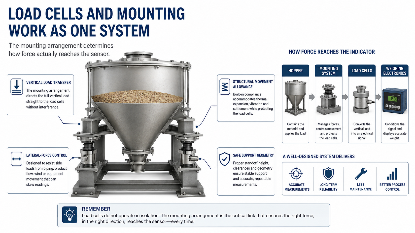
4. Load Cells and Mounting Hardware Work as One System
Selecting a hopper load cell is not only about capacity and accuracy.
The mounting arrangement determines how the force actually reaches the sensor.
A good mounting design needs to transfer vertical load correctly while controlling unwanted lateral forces and allowing reasonable structural movement.
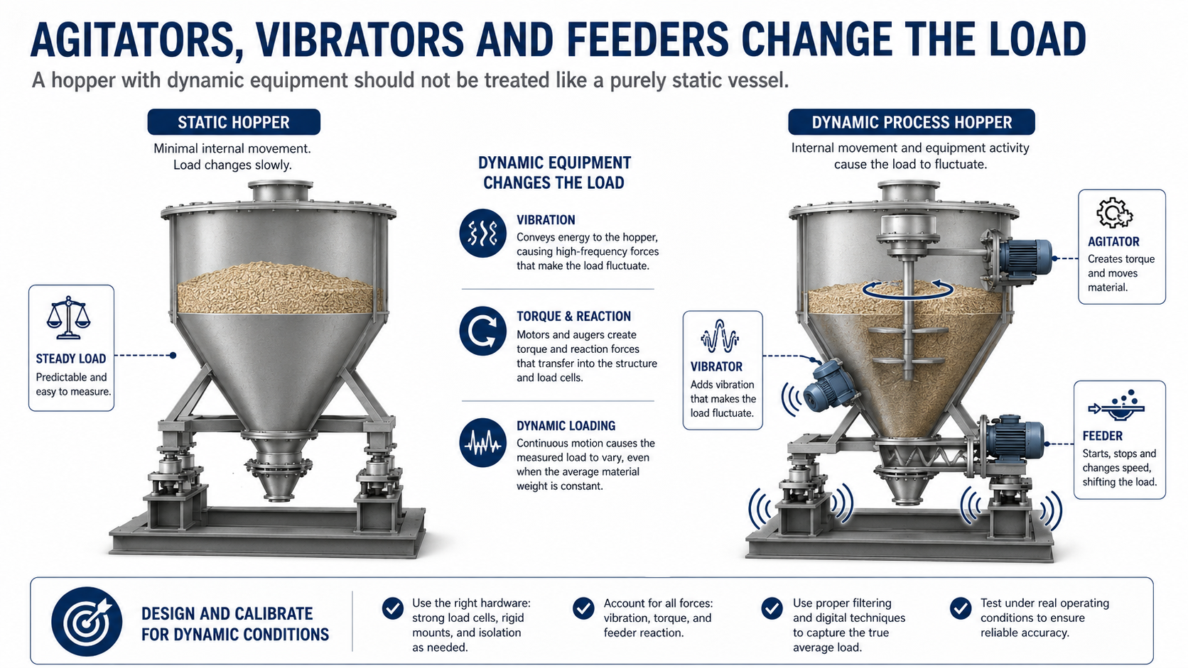
This becomes especially important when the hopper carries:
These devices can introduce vibration, torque and changing dynamic loads.
So:
The load cell and mounting hardware should be treated as one mechanical assembly.
5. Calibration Cannot Fix a Mechanical Problem
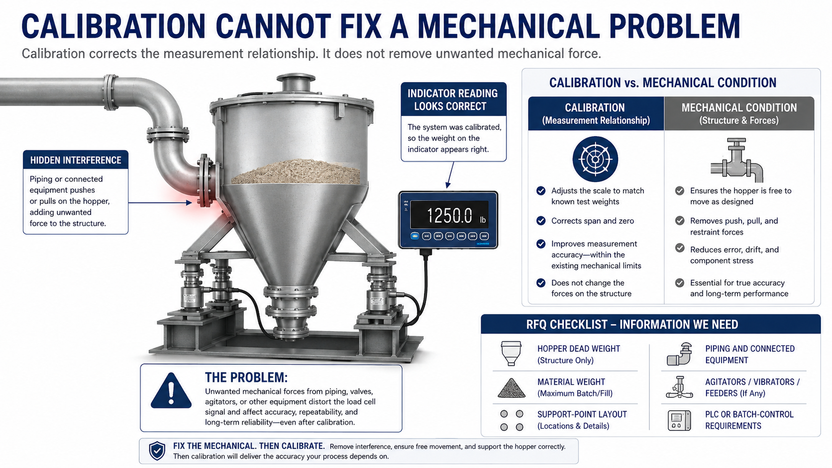
A system with piping interference can sometimes still be calibrated to display the correct weight at one particular moment.
The problem is that the external force may change.
Temperature, valve movement, filling level or pipe movement may all alter that force.
Then the original calibration is no longer compensating for the same condition.
So:
Calibration corrects the relationship between force and indicated weight. It does not remove unwanted mechanical force.
If a hopper weighing system repeatedly drifts or needs frequent recalibration, checking the mechanical connections may be more useful than immediately changing indicator settings.
6. What Buyers Provide — and What Engineers Also Need
| Basic Information | More Useful Engineering Information |
| Total hopper weight | Maximum realistic load at one support |
| Number of load cells | Actual support layout |
| Material capacity | Filling position and load distribution |
| Flexible connection | Actual stiffness and installation |
| Hopper drawing | Connected piping and equipment |
| Accuracy target | Mechanical condition + calibration method |
The key point is simple:
The total hopper weight does not define the whole weighing system. What matters is how the load actually reaches each sensor.
7. What to Send for a Hopper Weighing Quotation
A useful RFQ does not need to be long.
Provide:
- hopper dead weight
- maximum material weight
- support-point quantity and layout
- filling and discharge method
- agitators, vibrators or feeders, if any
- target accuracy
- PLC or batch-control requirements
Most importantly, attach a drawing showing all piping and equipment mechanically connected to the weighing vessel.
That drawing often reveals engineering conditions that cannot be seen from a load-cell datasheet.
If some information is not yet available, say so.
A capable supplier should identify the missing engineering information before finalizing the configuration.
8. From Keli Technology to KELISCALES Hopper Weighing
A hopper weighing system can be viewed as one complete load path:
Material → Hopper → Mounting System → Load Cells → Weighing Electronics → PLC / Batch Control
Keli’s weighing technology supports the sensing and measurement part of this chain.
KELISCALES extends that capability into complete hopper weighing applications.
Final performance depends on the complete load path, not one component alone.
9. Before the Hopper Is Built
Before finalizing the system, make sure a few practical questions have clear answers:
Which support point can carry the highest load?
What pipes or equipment push or pull on the hopper?
Can the vessel move without unnecessary mechanical restraint?
Are there dynamic forces from filling, agitation or vibration?
Once these conditions are clear, load-cell selection and calibration become much more straightforward.
A load cell does not know which force is “weight” and which force is “interference.” It measures whatever reaches the support point.

Need customized model matching your production line, technical drawings and accurate quotation?
Submit your inquiry now, our engineering sales team will send full solution within 24 working hours.