
A conveyor belt scale is often simplified as “a load cell under a conveyor.”
That description misses most of the system.
A belt scale has to do four things correctly:
transfer the material load, measure that load, measure actual belt travel, and combine both signals into flow rate and totalized weight.
If one stage stops representing the real process, the final result can be wrong even when the display looks stable.
For a closer look at the basic measurement principle, see how a conveyor belt scale works.
1. The Belt Scale Measurement Chain
The basic load path is:
Material → Belt → Weigh Idler → Weigh Frame (Weighbridge) → Load Cells
At the same time:
Belt Travel → Speed Sensor
The integrator then combines both measurements:
Load Signal + Speed Signal → Flow Rate → Totalized Weight
Each component answers a different part of the measurement problem.
The weigh frame controls how the load reaches the sensors. The load cells measure force. The speed sensor measures belt travel. The integrator performs the final calculation.
2. Weigh Frame: Controls the Force Path
The weigh frame is more than a support structure.
Its job is to transfer the material load to the load cells as consistently as possible.
A good load path is:
Material Load → Weigh Idler → Weigh Frame → Load Cells
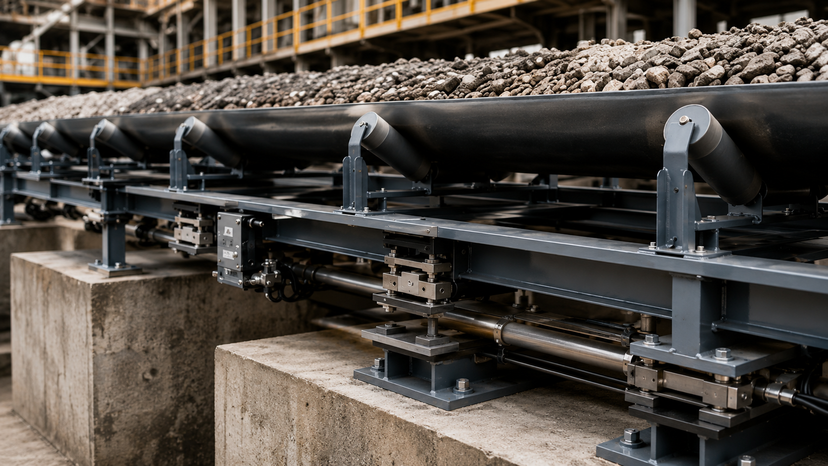
Problems begin when mechanical contact, buildup, poor alignment, friction, or structural restraint changes that path.
One important failure mode is force shunting.
A force shunt occurs when part of the material load follows an unintended mechanical path instead of passing through the load cells.
The scale may then read low. The opposite can also happen if an unwanted mechanical force enters the weighing structure and makes the reading high.
Mechanical contact and other load cell weighing errors should therefore be checked before assuming the sensor itself is faulty.
A useful rule is:
The weigh frame does not create the measurement. It determines whether the load cells receive the right load.
3. Load Cells: Measure Force, Not Material Flow
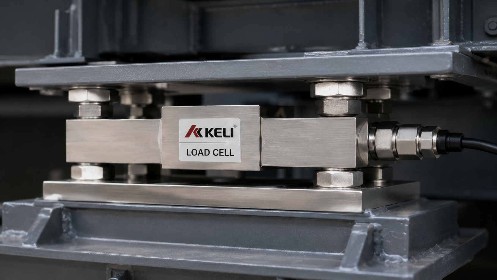
Load cells convert mechanical force into an electrical signal.
They do not calculate tons per hour.
A load cell does not know how fast the belt is moving, how much material has already passed, or whether the belt is moving at all.
For example, a fully loaded belt that is stopped can still produce a valid load-cell signal.
But the flow rate is: 0 t/h
because belt speed is zero.
This is why:
Load cells measure force. The complete system measures material flow.
KELISCALES belt weighing systems build on Keli load cell technology as the force-sensing stage of the system.
4. Speed Sensor: Must Represent Actual Belt Travel
The speed sensor provides the second measurement required for continuous belt weighing.
The basic relationship is:
Flow = Belt Load × Belt Speed
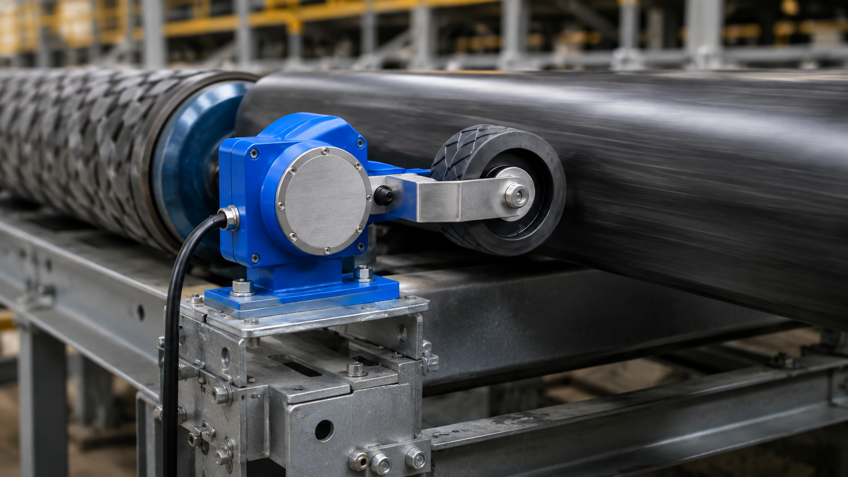
If the speed signal is 1% high, the calculated flow will also be approximately 1% high.
But a stable speed signal is not automatically an accurate one.
Problems can occur if a measuring wheel slips, an encoder coupling becomes loose, or the sensor measures drive motion rather than actual belt travel.
The important question is:
Does the speed signal represent the actual belt travel through the weighing zone?
A dedicated belt scale speed sensor is intended to provide this movement input for continuous flow calculation.
5. Integrator: Calculates From the Signals It Receives
The integrator combines the load and speed signals.
Typical functions include:
- flow-rate calculation
- totalization
- zero adjustment
- calibration factors
- alarms
- PLC communication
For example:
Belt load = 80 kg/m
Belt speed = 1.5 m/s
Then:
80 × 1.5 × 3.6 = 432 t/h
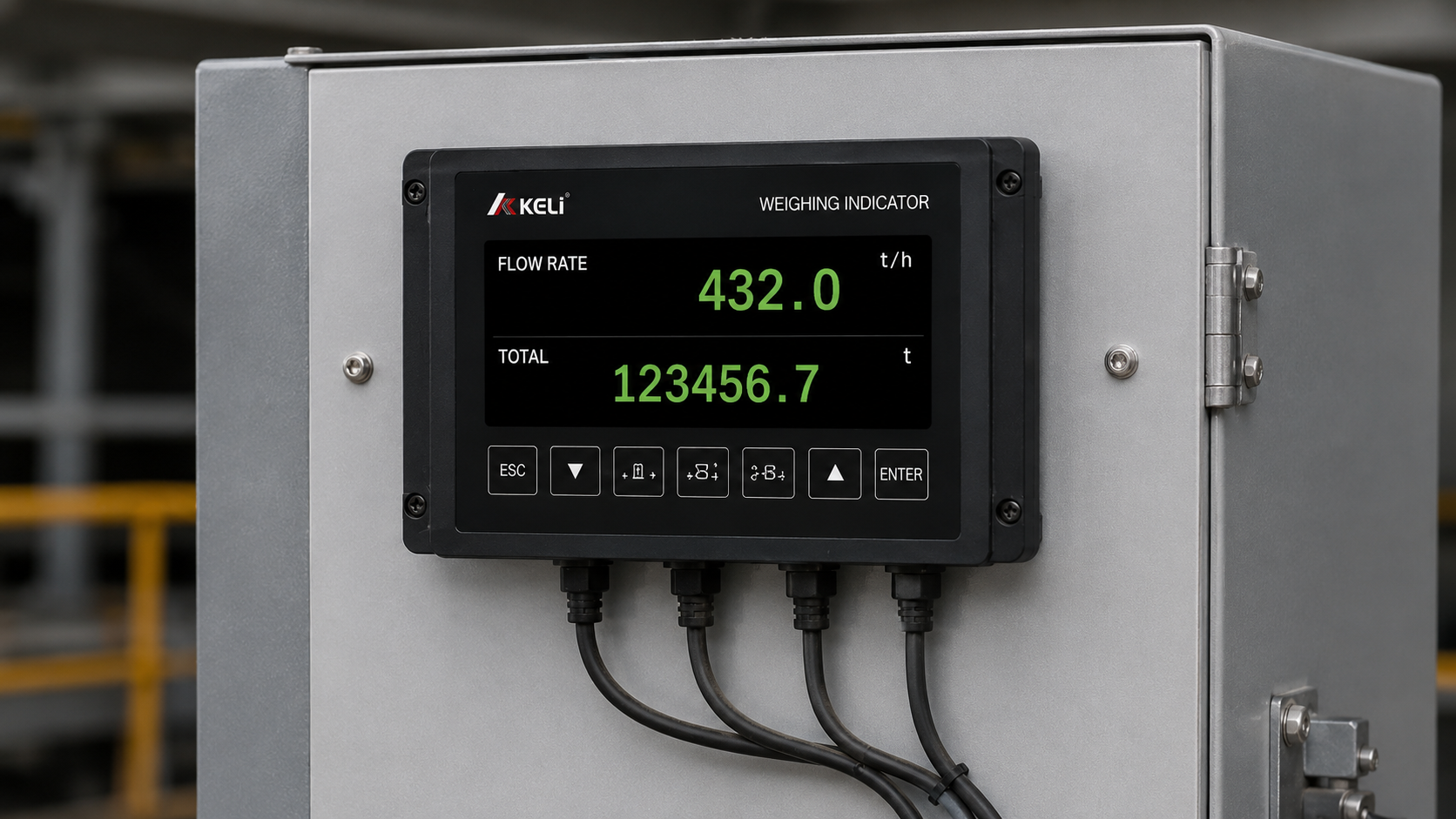
The integrator performs this calculation continuously as load and speed change.
But it cannot repair a bad input.
If the weigh frame is mechanically restricted, the load signal is wrong. If the speed sensor reads high, the speed input is wrong.
The controller may process both signals correctly and still produce the wrong result.
Zero and span settings should therefore be changed only after the mechanical and speed signals are stable. See how to calibrate a conveyor belt scale for the full calibration and verification process.
6. Small Components Can Still Cause Problems

Junction boxes, cables, connectors, shielding, and grounding can also affect signal quality.
Typical symptoms include:
- noisy zero
- sudden jumps
- intermittent readings
- unexplained drift
If an error repeats at the same point every belt revolution, look first for a mechanical or belt-related cause.
If the signal jumps randomly with no clear relationship to belt position or loading, the electrical signal path should also be checked.
7. Which Component Should You Check First?
| What You See | Check First |
| Reading changes after idler work | Weigh frame and idler alignment |
| Stable load signal but wrong t/h | Speed sensor |
| Zero becomes noisy or intermittent | Load cells, junction box, cables |
| Error changes with off-center loading | Weigh frame and load-cell arrangement |
| Electronic calibration passes but material test fails | Mechanical load path |
| Error changes with belt speed | Speed measurement |
| Flow looks correct but totalized weight is wrong | Integrator settings |
This table is not a fixed fault code. It is simply a way to narrow the investigation before replacing parts.
8. Which Component Determines Belt Scale Accuracy?
No single component does.
Overall conveyor belt scale accuracy depends on how well the complete measurement chain works together.
A precise load cell cannot correct a force shunt.
A good controller cannot fix a slipping speed sensor.
A stable speed signal cannot compensate for poor weigh-frame geometry.
So:
Belt scale accuracy depends on the complete measurement chain, not the specification of one component.
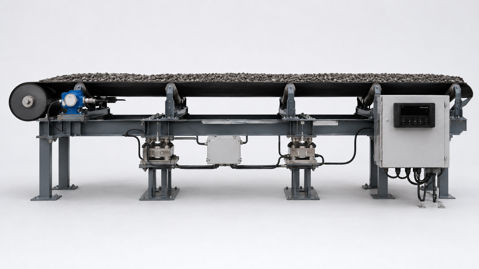
9. How the LCS-Series Uses the Measurement Chain
The LCS-Series high-accuracy conveyor belt scale uses a floating-balance weighing structure with dual Keli load cells.
The structure is designed to minimize unnecessary force-transfer links, while the dual-load-cell arrangement helps reduce sensitivity to off-center loading.
A dedicated speed sensor provides the belt-travel signal, and the controller combines load and speed information to calculate flow rate and totalized weight.
The important point is not simply that the system contains several components.
It is that each component has to preserve a different part of the real conveyor process.
10. The Main Point
A conveyor belt scale is best understood as four linked functions:
Force Transfer → Force Measurement → Belt Travel Measurement → Calculation
When the result becomes unreliable, ask:
Is the material load reaching the load cells correctly?
Does the speed signal represent actual belt travel?
Is the controller calculating from correct inputs?
That approach usually finds the problem faster than assuming the load cell must be the cause.

Need customized model matching your production line, technical drawings and accurate quotation?
Submit your inquiry now, our engineering sales team will send full solution within 24 working hours.